January 18, 2024
To improve the maintenance level of substation secondary equipment, it is necessary to visualize the equipment, provide multi-dimensional visual information support, decision-making and safe operation for the daily operation and maintenance, abnormality handling, accident analysis and maintenance of substation secondary system, and develop advanced applications based on the operation and maintenance platform to improve the level of equipment refinement management.
The substation intelligent operation and maintenance management platform obtains information from the process layer network and station control layer network, highly integrates the information related to operation and maintenance, realizes the applications of visualized online monitoring and intelligent diagnosis, and supports remote uploading. Its main functions include multi-dimensional operation and maintenance management, such as online monitoring, condition assessment and monitoring and warning of secondary equipment, fault localization, auxiliary safety measures for secondary maintenance, configuration file management, protection value management, fault information management and comprehensive analysis.
AcrelCloud-1000 substation operation and maintenance cloud platform
AcrelCloud-1000 substation operation and maintenance cloud platform based on Internet +, big data, mobile communications and other technology development of the cloud management platform, to meet the needs of users or operation and maintenance companies to monitor the operating status and parameters of many substation circuits, indoor environmental temperature and humidity, cable and busbar operating temperature, on-site equipment or environmental video scenes, etc., to achieve a center of the data, centralized storage, unified management, easy to use, to support the user with the right to access through the computer, cell phone, PAD and other types of terminal links, receive alarms, and to complete the relevant equipment, such as daily and regular inspections and dispatches, etc., management.
It is applicable to the new construction, expansion and reconstruction of power distribution operation and maintenance system in telecommunication, finance, transportation, energy, medical and health care, culture and sports, education and scientific research, agriculture, forestry and water conservancy, commercial services, public utilities, electronic industrial park and other industries.
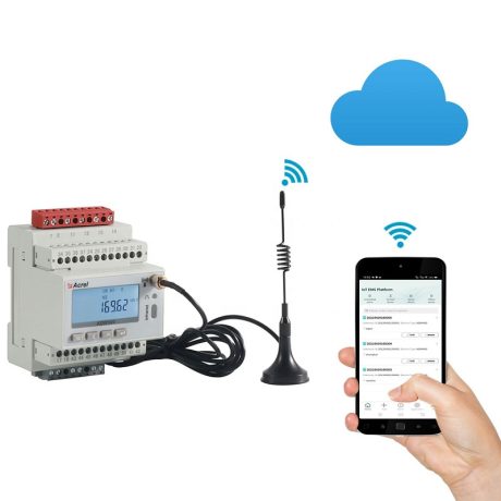
A set of intelligent gateway is installed in the substation distribution room to collect the data of intelligent equipment in the substation room, and after protocol conversion, compression and encryption, it is uploaded at regular intervals or uploaded to the platform in a triggered manner.
The platform can complete the data exchange of all the intelligent equipments in the substation and distribution room, and it can real-time monitor the operation status of transformers, circuit breakers, and other important operating equipments in the substation; it can real-time monitor the operation data of the circuits in the substation and distribution room as well as the digital quantities of the ambient temperatures etc.; and the communication and management unit is connected with the plant's local area network (LAN) and passes the data to the data center.
AcrelCloud-1000 substation operation and maintenance cloud platform provides user profiles, power data monitoring, power quality analysis, power consumption analysis, daily, monthly and annual energy consumption data reports, abnormal event alarms and records, operating environment monitoring, equipment maintenance, user reports, Operation and maintenance dispatching and other functions, and supports multi-platform and multi-terminal data access.
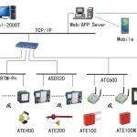
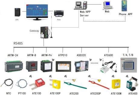
The AcrelCloud-1000 substation operation and maintenance cloud platform system can be divided into four layers: perception layer, transmission layer, application layer and display layer.
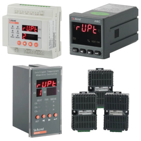
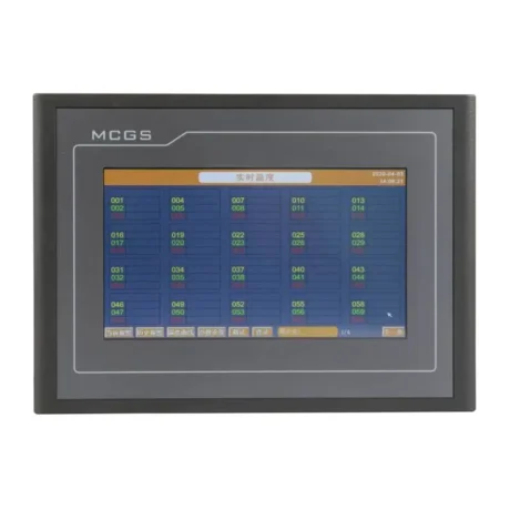
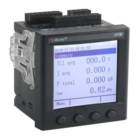
①Perception layer: includes multi-functional instruments, temperature and humidity monitoring devices, cameras, switching quantity acquisition devices, etc. installed in the substation. In addition to the camera, other devices are connected to the RS485 port of the on-site smart gateway through the RS485 bus.
②Transport layer: includes on-site intelligent gateways, switches and other equipment. The intelligent gateway actively collects data from on-site device layer devices, performs protocol conversion, data storage, and uploads the data to the designated server port through the switch. When the network fails, the data can be stored locally and resumed from the interrupted location when the network recovers. Upload data to ensure that server-side data is not lost.
③Application layer: includes application server and database server. If the number of substations is less than 30, the application server and database server can be configured in one. The server needs to have a fixed IP address to receive data actively sent by each smart gateway.
Display layer: Users access platform information through multiple terminals such as mobile phones, tablets, computers, etc.
1 Real-time monitoring
Click on the power distribution circuit to view detailed power consumption data, generate power operation reports, and query historical data and environmental data monitoring of various power parameters, voltage, current, power, harmonics, etc.
2 Monthly energy consumption report
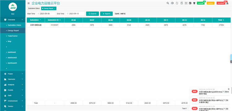
The monthly energy consumption report allows users to query the electricity consumption of managed stations based on total electricity consumption, substation name, substation number, etc. The query span can be set to months.
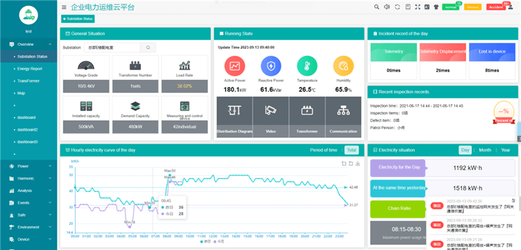
3 Site monitoring
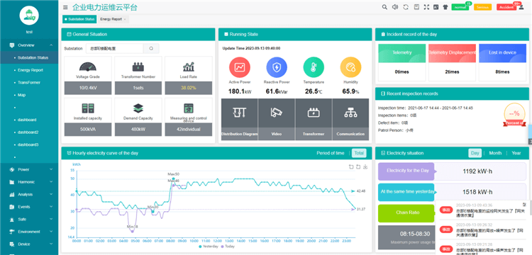
Site monitoring includes overview, operating status, event records of the day, hourly power consumption curve of the day, and power consumption overview.
4 Transformer status
Transformer status supports users to query the transformer power, load factor, and other operating status data of all or a certain station, and supports ranking in ascending or descending order by load factor, power.
5 Power operation and maintenance
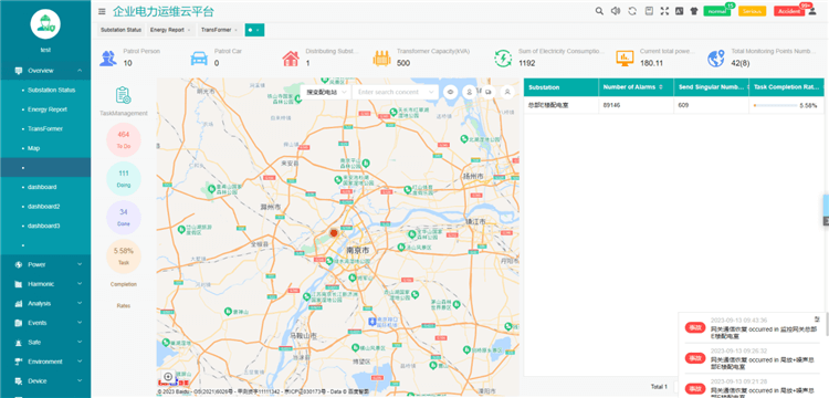
Operation and maintenance displays the location and total amount information on the substation map currently managed by the user.
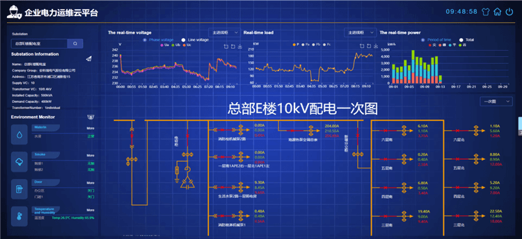
6 Power distribution diagram
The power distribution diagram displays the power distribution information of the selected substation. The power distribution diagram displays the switching status, current and other operating status and information of each circuit, and supports detailed operating parameter queries such as voltage, current, and power.
7 Video surveillance
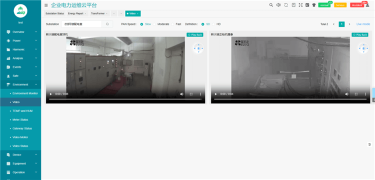
Video surveillance displays the current real-time picture (video live broadcast). By selecting a certain power transformation and distribution station, you can view the video information in the power transformation and distribution station.
8 Power operation report
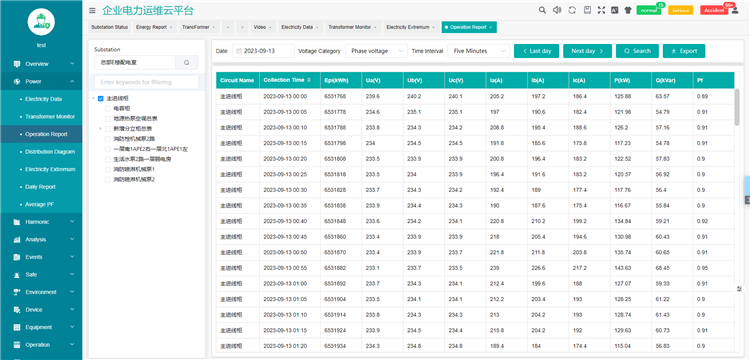
The power operation report displays the real-time values and average row statistics of the specified collection interval operating parameters of each circuit of the selected equipment in the selected station and the electric energy meterreading.
9 Fault alarm
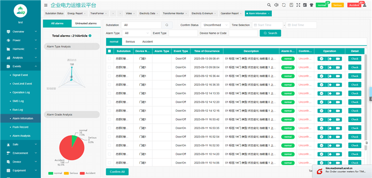
Telemetry, remote signaling alarm (webpage and SMS), upper and lower alarm limits can be set, alarm for substation operating environment (flooding, smoke, etc.)
10 Task management
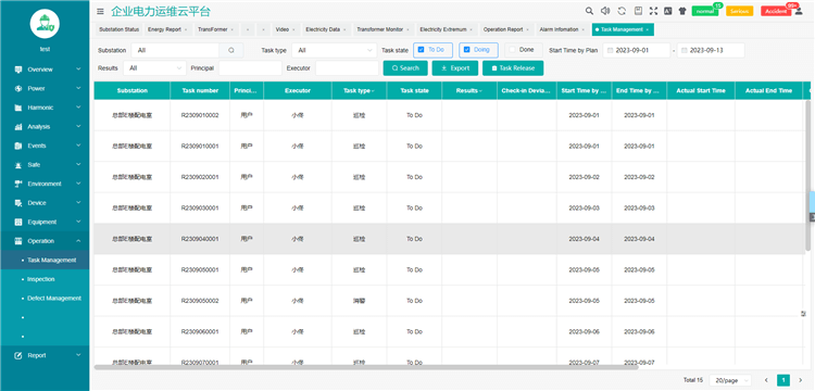
The task management page can publish inspection or defect elimination tasks, check the status and completion of inspection or defect elimination tasks, and click View Task to view specific inspectionin information
11 User Report
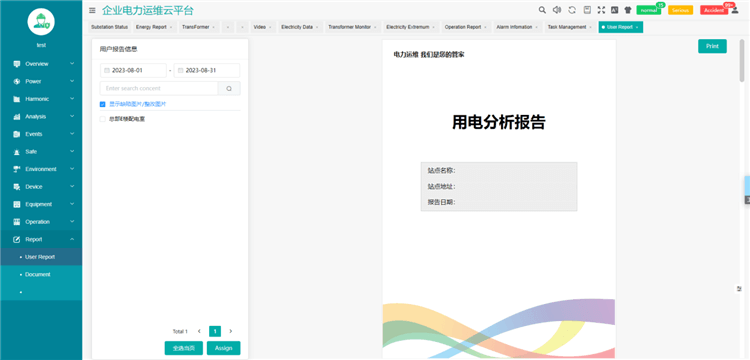
The user report page is mainly used to automatically summarize a month's operation data of the selected transformer and distribution station, perform statistical analysis on transformer load, distribution circuit power consumption, power factor, alarm events, etc., and list them within that period. Various types of defects discovered during inspections and their treatment.
ucture, optical fiber ring network structure,According to the user's power consumption scale, distribution of power consumption equipment and floor area, etc, the networking mode is comprehensively considered.
The application of the intelligent substation operation and maintenance management platform can transform the existing transmission and maintenance modes into remote online diagnosis of actual operating conditions and targeted inspections based on the health status of the equipment, greatly reducing the number of operation and maintenance personnel. Conduct operation, maintenance and inspection frequency of on-site relay protection devices to improve the level of refined management of equipment. The research on remote intelligent operation and maintenance technology of relay protection is of great significance.
Kindly Fill out the Form below and tell us more about your Requirements,
We would like to provide Suitable Solution for You.
or Send us Email directly, [email protected]
EN 61010:2010+A1:2019
EN 61326-1:2013
EN 61000-3-2:2019
EN 61000-3-3:2013+A1:2019

2014/30/EU
EN IEC 61000
IEC 62052
IEC 62053
 Standard Lead Time:
Sample: 2 days
Bulk: 1 month
CE
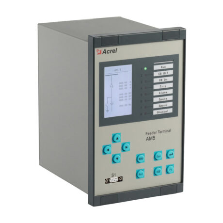
8 current input, 4 voltage input
16 DI, 10 DO
2 RS485, 1 RS232, 1 GPS
Powerful graphic programmable Logic
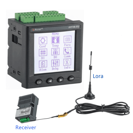
Communication Distance: 150m in open Area & 15m in Building
Extra RS485 Communication: MODBUS-RTU
DO/DI Function: 2 Over-temp Alarm Relay Outputs & 4 Digital Inputs
Electric Parameter Measurement: U,I,P,Q,F,kWh,kVarh (Optional)
2014/35/EU
2014/30/EU
Standard Lead Time:
Sample: 2 days
Bulk: 1 month


Kindly Fill out the Form below and tell us more about your Requirements,
We would like to provide Suitable Solution for You.
or Send us Email directly, [email protected]