April 20, 2022
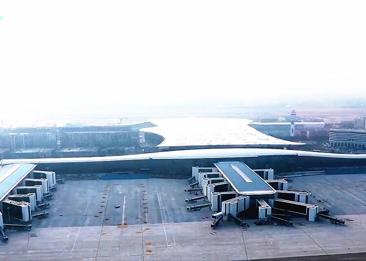
Hangzhou Xiaoshan International Airport currently has three terminals, T1, T2, and T3, with a designed annual passenger throughput of 33 million, which will rise to 40 million after subsequent reconstruction and expansion. The newly built T4 terminal building will have an area of 720,000 square meters after the completion of the three-stage construction, and the designed annual passenger throughput will reach 50 million.
The main construction contents of the terminal building bid section of the third phase of the project include the passenger terminal building and the north third finger corridor, the development of underground space, the expansion of the original building, the road, the elevated road in front of the new building, the garage tunnel of No. 1 Road, and the comprehensive pipe corridor , Sewage pumping stations, etc. The total construction area of the project is about 670,000 square meters, of which the terminal building has two floors underground and four floors above the ground (partially five floors). The long corridor and the three finger corridors in the north, the main floor is about 440 meters wide and 205 meters deep, the width of the three finger corridors is 42 meters, and the width of the two horizontal corridors is 22 meters. There are planned subway and high-speed rail passages passing through the lower part of the main building area of the terminal, and the terminal building structure is jointly built with the high-speed rail and subway structures.
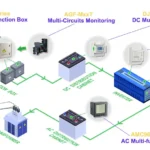
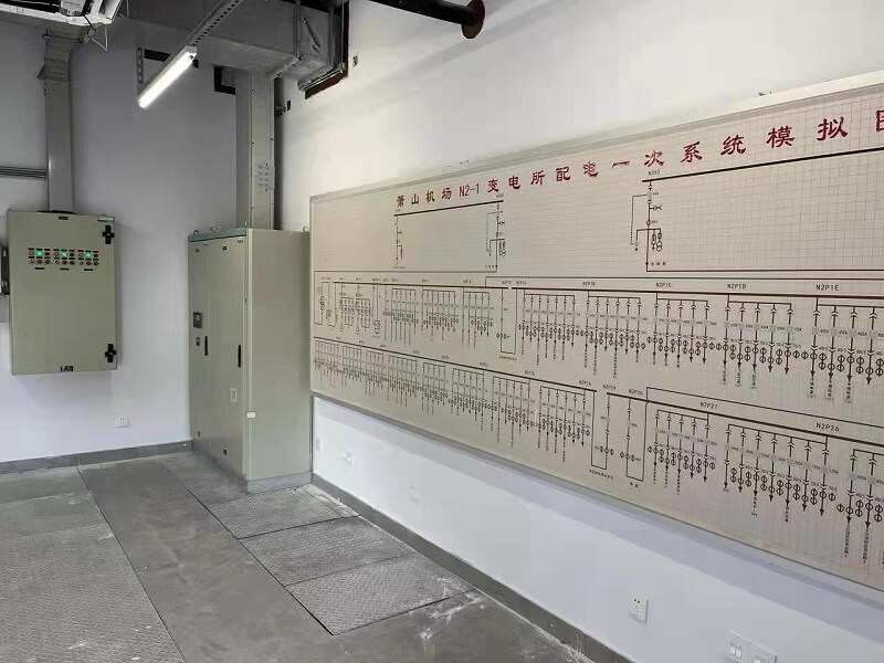
This project is the third phase project of Hangzhou Xiaoshan International Airport. The project system includes 6 substations, namely the terminal building, the south corridor, the corridor corridor, the transportation center, the energy center and the passenger overnight room.
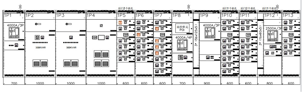
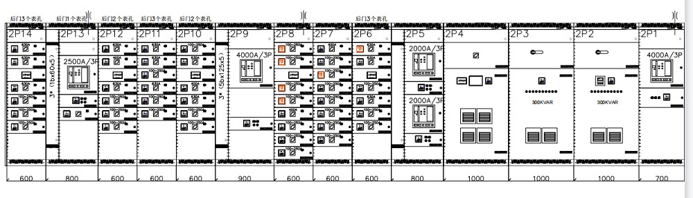
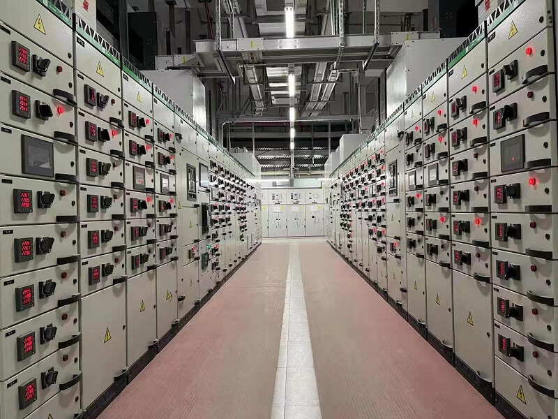
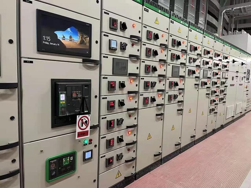
The terminal building includes power distribution rooms C1~C6, with a total of 301 low-voltage cabinets and 80 UPS cabinets. The low-voltage side is operated with two incoming lines and one bus tie. The south corridor includes S1-S2 power distribution rooms, a total of 36 low-voltage cabinets and 9 UPS cabinets, and most of the low-voltage sides are operated with two incoming lines and one bus tie. Corridors and corridors include power distribution rooms N1~N4, with a total of 191 low-voltage cabinets and 24 UPS cabinets. Most of the low-voltage sides operate in the mode of two incoming lines and one bus tie. The transportation center includes N1~N3 OC~OD S1~S3 power distribution rooms, with a total of 282 low-voltage cabinets, and most of the low-voltage sides are operated with two incoming lines and one bus tie. The energy center has a total of 62 low-voltage cabinets, and most of the low-voltage sides operate in the mode of two incoming lines and one bus tie. The passenger overnight room includes power distribution rooms in Building A and Building B, with a total of 117 low-voltage cabinets, and most of the low-voltage sides are operated with two incoming lines and one bus tie. All low-voltage power distribution cabinets in all substations are equipped with wireless temperature measurement and cabinet display devices, which fully guarantee the safe and reliable operation of the system.
For the third phase expansion project of Hangzhou Xiaoshan International Airport, wireless temperature measurement products need to be configured.
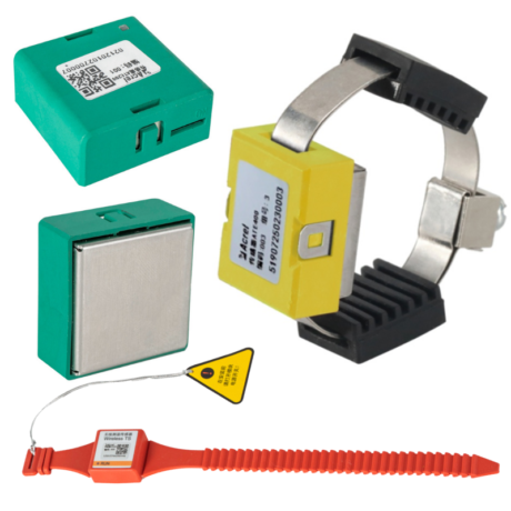
1) Non-battery-powered (powered by induction) wireless temperature sensor
2) Wireless frequency: 470MHz;
3) Starting current: ≥5A;
4) Temperature measurement range: -50 ℃ ~ +125 ℃;
5) Sampling frequency: 15s;
6) Transmission frequency: 15s;
7) Accuracy: ±1°C;
8) Working temperature: -40 ℃ ~ +85 ℃;
9) Working current: primary rated current 5000 A;
10) Temperature rise requirements: Under rated working conditions, the device should not reach a temperature that may affect the insulation of the primary equipment of the switchgear and the normal operation of the measured point. The current transformer coil of the device passes through 1250 A for 30 minutes, and the ambient temperature is 20 ℃ , the surface temperature rise of the wireless temperature sensor should not exceed 10K.
11) Transmission distance: the open distance is not more than 150 meters.
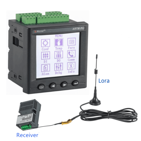
1) Working power supply: DC 24V
2) Transmission distance: the open distance is not more than 150 meters;
3) Communication interface: 1 RS485 serial communication interface, Modbus-RTU communication protocol;
4) Installation method: 35mm rail type
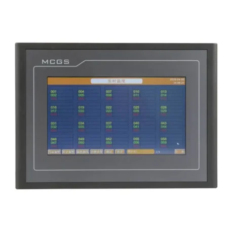
1) Working power supply: DC 24V;
2) Power consumption: ≤8 W;
3) Number of measuring points: no less than 240 points;
4) Communication interface: 1 RS485 serial communication interface (Modbus-RTU protocol) and 1 Ethernet port as standard;
5) Measurement accuracy: ±1 ℃;
6) High temperature alarm: the device comes with a buzzer, and the buzzer will be activated when the temperature exceeds the set value;
7) Data alarm records: not less than 120;
8) The device should have an alarm output function, and the user can set the warning and alarm temperature values according to the needs.
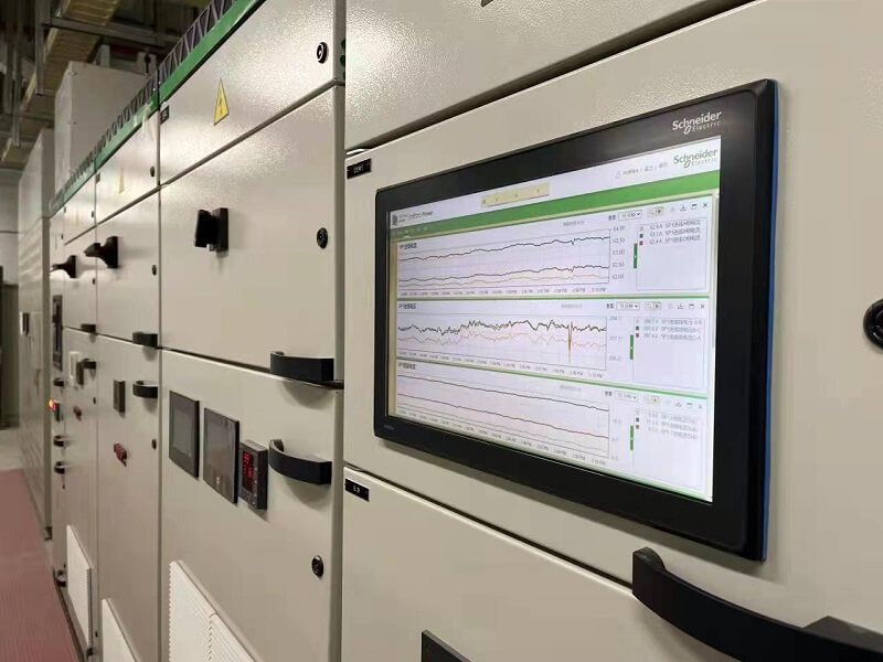
9) The device should have real-time temperature measurement function, temperature curve function, and data storage function.
After the touch screen is powered on and enters the working state, the default is the "real-time temperature" interface, and then this interface can observe the temperature values collected by each node.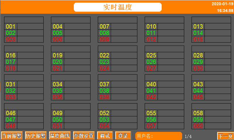
After the user "logs in" (the default login password of "user" is 0008, which can be modified through the login interface), the high temperature alarm value and name of the wireless temperature sensor group can be set through the "Parameter Settings" menu. When the measured temperature value exceeds the set When the value is set, the touch screen will display an alarm and the buzzer will sound; at the same time, Chinese and English language switching can be set. After setting the parameters, be sure to click the "Save Settings" button, otherwise the set value will not be successful.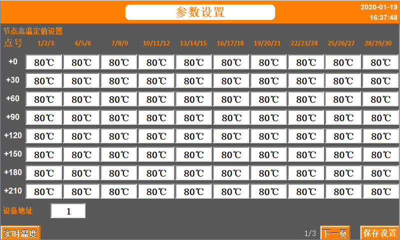
Enter the "Current Alarm" interface, which displays the current alarm occurrence; if you want to view all historical alarms, enter the "Historical Alarm" interface. View real-time alarms on the "Current Alarm" interface. When there is an alarm, the interface will display an alarm prompt and the buzzer will sound. The word color of will change to blue, and when the alarm fault is eliminated, the alarm prompt will disappear.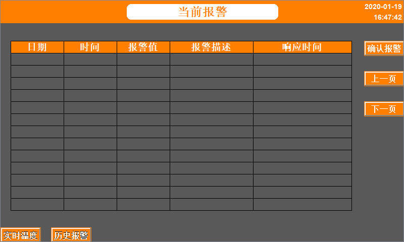
Enter the "Temperature Curve" interface, each page has 12 curves, a total of 20 pages. The temperature is recorded every 5 minutes and can be stored for 300 days. Specific curve requirements can be adjusted on the screen.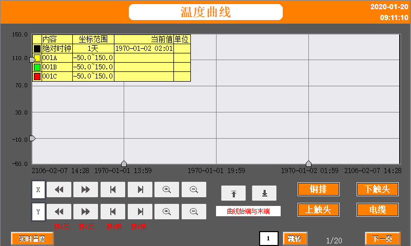
6-point temperature measurement on the frame circuit breaker of the low-voltage incoming bus-connection cabinet, 3-point temperature measurement on the compensation active filter cabinet, and 3-point temperature measurement on the energy circuit of the outgoing line drawer cabinet.
The wireless temperature measurement transceiver and power module are installed in the cable room in the cabinet, and the touch screen cabinet is embedded in the installation.
Kindly Fill out the Form below and tell us more about your Requirements,
We would like to provide Suitable Solution for You.
or Send us Email directly, [email protected]
CE
RED
Radio Equipment Directive (RED) 2014/53/EU


Communication Distance: 150m in open Area & 15m in Building
Extra RS485 Communication: MODBUS-RTU
DO/DI Function: 2 Over-temp Alarm Relay Outputs & 4 Digital Inputs
Electric Parameter Measurement: U,I,P,Q,F,kWh,kVarh (Optional)
CE


Kindly Fill out the Form below and tell us more about your Requirements,
We would like to provide Suitable Solution for You.
or Send us Email directly, [email protected]